مشاورين وبلاگ

با عرض سلام واحترام و تشکراز لطف تمامی همکاران و علاقمندان،

متاسفانه درحال حاضرقادربه پاسخگویی به سوالات نمیباشم.درصورت تمایل به مباحث  مطالعات الکتروفیزیولوژی قلب میتوانید دردوره هایی که  انجمن قلب پرستاری ایران در بیمارستان قلب شهیدرجایی برگزار مینماید شرکت بفرمایید.

موفق باشید


آنالیز و برنامه ریزی پیس میکر و دفيبريلاتور كاشتني

به زودي تايپ خواهد شد ......

تکنولوژی های جدید در علم الکتروفیزیولوژی

v   امروزه اکثر پروسیجرهای الکتروفیزیولوژی و Ablation بصورت Manual انجام میگردد و نیازمند آنست که پزشک با جابجایی های متعدد کتتر، مکان مناسب جهت قرارگرفتن آنرا پیدا نماید و درصد موفقیت این پروسیجرها براساس دسترسی پزشک به این نقاط تماس، متفاوت است و همچنین این کار نیازمند آنست که پزشک گاهاً تا چند ساعت بصورت ایستاده در معرض X-Ray باشد.

تکنولوژی جدید SensiX Robotic Catheter System همراه با EnSite System از کمپانی St.Jude Medical این امکان را به پزشکان میدهد که محل قرارگرفتن کتتر را بصورت 3 بعدی مشاهده نمایند و همچنین کتتر را بصورت ربوتیک به محل مناسب هدایت کنند. در نتیجه ضمن کوتاه شدن زمان پروسیجر درصد موفقیت بیشتر میشود.

v   امروزه در درمان AF از روشها و تکنیکهای متفاوتی با منابع انرژی شامل رادیو فرکانس، کرایوترمی و لیزر استفاده میگردد. استفاده از High Intensity Microwave بر پایه اولتراسوند در دست مطالعه است .  تکنولوژی ساخت کتترها نیز روبه تکامل است که منجر به افزایش میزان موفقیت و کاهش عوارض جانبی می گردد . Single point RF که توانایی ارسال انرژی از نوک کاتتر را دارند، Multi electrode RF توانایی ارسال انرژی از چند کانون را دارند و Contact Force Sensing RF که پزشک را از میزان تماس و فشار وارده به کتتر آگاه می سازد.

v      Wireless Cardiac Stimulation System (Wics)  نسل جدید پیس میکرهای بدون لید

در این سیستم یک رسیور بسیار کوچک (I mm ×10 mm) در قلب Implant میگردد. این رسیور ذاتاً توانایی تولید الکتریسیته ندارد و تمام قدرت خود را بصورت بی سیم دریافت میکند.

سیگنالهای اولتراسونیک از پیس میکری که در بالای دنده ها تعبیه شده به رسیور میرسد و رسیور سیگنالهای دریافتی را به سیگنالهای الکتریکی تبدیل کرده و قلب را تحریک مینماید.

این نسل جدید پیس میکر در ابتدا بصورت تک حفره و دو حفره و سپس درمورد CRT استفاده خواهد شد.

v     باطریهای جدید پیس میکر:

یکی از مشکلات بزرگ کمپانی های سازنده پیس میکر ایجاد تغییراتی در باطری پیس میکر است تا ضمن طولانی تر کردن طول عمر ژنراتور، ایمن  و بی خطر باشد. امروزه روش های جدیدی جهت تولید پیس میکر با منابع جدید انرژی در دست بررسی است.

-  گروهی از مهندسین دانشگاه میشیگان به مدیریت امین کرمی در حال ساخت پیس میکری هستند که انرژی لازم خود را از تحریکات و لرزشهای ناشی از ضربان قلب در قفسه سینه میگیرد و آنرا به انرژی الکتریکی تبدیل میکند. این انرژی 8 برابر انرژی مورد نیاز یک پیس میکر برای تحریک قلب میباشد.

-  Philippe Cinquin و همکارانش انرژی لازم جهت پیس میکر را از طریق یک ترانزیستور پیشرفته از طریق ATP سلولی تأمین می کنند این روش فعلاً در نمونه حیوانی انجام شده و نیاز به مطالعه بیشتر دارد.

قطعاً در آینده نه چندان دور شاهد تغییرات بسیار زیادی در زمینه تکنولوژیهای مورد استفاده در درمان بیماران خواهیم بود.

آموزش کار با دستگاه انسايت نووكس

تعداد بسياري از دوستان به دنبال روش يادگيري كار با دستگاه سه بعدی اینسایت هستند در لینک ذیل میتوانید اموزش گام به گام آن را ببینید.امیدوارم برایتان مفید باشد.لطفا به خاطر داشته باشید


http://www.alloro.biz/demo/SJM-EnSite-6/player.html

دستگاه نقشه بردار سه بعدیEnsite Navx

دستگاه نقشه بردار الکتروآناتومیک قلب(Ensite Navx) راهکاری نوین در شناسایی و درمان آریتمی های قلبی


دستگاه انسایت نوکس(ساخت شرکت سن جود مدیکال آمریکا) قادر به نمایش سه بعدی موقعیت کاتترهای داخل قلبی با استفاده از پچ های پوستی متعامد با جریانkHz  5.6 می باشد. ولتاژ و امپدانس بدست آمده از هر کاتتر توسط این جریان فاصله کاتتر تا هر پچ پوستی را مشخص می کندو درنهایت موقعیت هر کاتتر در داخل قلب به کمک الکترود مرجع محاسبه شده و نمایش داده می شود.همچنین آرتیفکت حرکتی ایجاد شده توسط تنفس بیمار  به کمک پردازشگرهای قوی به حداقل برسد.


          به طورکلی استفاده از نوکس در درمان آریتمی ها 4 مزیت عمده زیر را دارد.

1-نمایش موقعیت کاتترهای مختلف داخل قلبی به صورت زمان واقعی2-نمایش دقیقی از آناتومی قلب بیماربه صورت سه بعدی3-کاهش زمان فلوروسکوپی،کاهش میزان دزگیری بیمار و پرسنل وکاهش زمان روند درمان41-سازگاری آن با هر نوع دستگاه الکتروفیزیولوژی متداول

1. Earley M, Showkathali R, Alzetani M, Kistler P, Gupta D, Abrams D, et al. Radiofrequency ablation of arrhythmias guided by non-fluoroscopic catheter location: a prospective randomized trial. Eur Heart J. 2006;27:1223-9.

از معایب آن محدودیت در استفاده برای آریتمی های غیر پایدار می باشد،اگرچه که با استفاده از روش نقشه برداری غیرتماسی با نوکس تا حد زیادی این مشکل رفع شده است ،و نیز از مشکلات دیگر آن دقت نه چندان زیاد آن درترسیم آناتومی ساختارهای پیچیده است که این مشکل را نیز میتوان با انجام نقشه برداری دقیق و نقطه به نقطه با تماس مناسب کاتتر ها با بافت رفع کرد.2

 2. Packer D. Three-dimensional mapping in interventional electrophysiology: techniques and technology. J Cardiovasc Electrophysiol. 2005;16:1110-6.


مقایسه سیستمهای نقشه برداری

مشخصات


Fluoroscopy

EGM

Ensite navx


روش مکانیابی کاتتر ابلیشن

فلوروسکوپی اشعه ایکس


میدان الکتریکی

میدان الکتریکی


ترسیم سه بعدی حفره های قلب


خیر

خیر

بله

هدایت با محاسبات کامپیوتری


خیر


بله

بله

نمایش اطلاعات آناتومیکی قلب

بله

خیر

بله


نمایش اطلاعات الکتریکی قلب


خیر

بله

بله

نمایش تلفیقی اطلاعات آناتومیکی

 و الکتریکی قلب

خیر

خیر

بله


نیازمند فلوروسکوپی اشعه ایکس

 برای نقشه برداری قلبی و ابلیشن

بله

بله

خیر


کاهش میزان دز و زمان فلوروسکوپی در صورت استفاده از دستگاه نوکس

. با توجه به مقدار کم اما بالقوه خطرناک اشعه یونیزان برای بیماران و پرسنل کت لب، روش نقشه برداری الکترواناتومیک قلبی غیرفلوروسکوپیک با دستگاه نوکس  به منزله یک فرایندبسیار موثر مهم می باشد، به خصوص برای فرایندهای زمان بر که بیمار زمانهای طولانی تحت اشعه دستگاه فلوروسکوپی قرار می گیرد، مانند ابلیشن فیبریلاسیون دهلیزی (AF) و یا تاکی کاردی بطنی.به طور کلی نوکس هم با کاهش زمان فلوروسکوپی ،کاهش مقدار پرتوگیری بیماران و پرسنل،و کاهش زمان روند درمان نقش بسزایی را در بخش الکتروفیزیولوژی به عهده می گیرد.12

12. Estner H, Deisenhofer I, Luik A, Ndrepepa G, von Bary C, Zrenner B, et al. Electrical isolation of pulmonary veins in patients with atrial fibrillation: reduction of fluoroscopy exposure and procedure duration by the use of a non-fluoroscopic navigation system (NavX).Europace. 2006;8:583-7.

نتیجه مطالعات هفت گروه تحقیقاتی  در زمینه میزان دز و زمان فلوروسکوپی درروند ابلیشن بدون دستگاههای نقشه بردار الکتروآناتومیک برای آریتمی های مختلف به این صورت بوده است که میانگین زمانی برای آریتمی های AFL,AVNRT بین 20 تا 67 دقیقه و برای فیبریلاسیون دهلیزی (AF)  بین 57 تا 129 دقیقه می باشد.لیکفت و همکاران65 دز ورودی پوست را در عمل ابلیشن 3 برابر بیشتر از AFLو AVNRT گزارش کردند.

65. Lickfett L, Mahesh M, Vasamreddy C, Bradley D, Jayam V, Eldadah Z et al. Radiation exposure during catheter ablation of atrial fibrillation. Circulation 2004; 110(19): 3003-3010


استفاده از نقشه ولتاژ برای شناسایی مناطق ایسکمیک و مرزی و درمان تاکیکاردی ایسکمیک بطنی

تاکیکاردی ایسکمیک بطنی ریتم غیر طبیعی و سریع قلبی است که از بطنها ایجاد می شود.مکانیسم اولیه آن ورود مجددهای پالسهای الکتریکی قلب با ابعاد بزرگ است،که در نتیجه اختلال در عبور پالس به خاطر وجود بیماری در بافت قلبی می باشد.ایسکمیک های ورود مجدد در بیمارانی که دچار سکته قلبی شده اند یا مشکلات و بیماریهای  بافت میوکارد دارند شایع بوده و محل تشکیل  ورود مجدد های بطنی در مرز بافت سالم و بافت غیرنرمال میوکارد قلب رخ می دهد.این گونه تاکیکاردیها،یا تک شکلی(دارای یک مسیر ورود مجدد) بوده یا چند شکلی(دارای چندین مسیر ورود مجدد)می باشد.مطالعات الکتروفیزیولوژی در در بیمارانی که ورود مجدد های چند شکلی پایدار دارند بسیار می تواند مفید باشد.اما در بیمارانی با تک شکلی ناپایدار یا فیبریلاسیون بطنی اولیه تاثیرکمتری دارد.

این بیماری یکی از عوامل مرگ ناگهانی بیمارمی باشد بطوریکه پس از سکته قلبی اولیه مرگ ناگهانی پس از ماهها یا سالها می تواند اتفاق بیفتد.

دستگاه نوکس با اختصاص رنگهای متفاوت به ولتاژدریافتی دیواره های قلب روش نوینی را برای جداسازی بافت اسکار از بافت سالم ارائه داده است ،اساس کار در در مان تاکیکاردی ایسکمیک بطنی قلب بر این استوار است که مسیر پالسهای ورود مجدد قطع شود ،که این کار مستلزم نقشه دقیق و سه بعدی از بافت اسکار ،بافت سالم و مرز این دو ناحیه می باشد.در این روش ولتاژهای دریافتی از کاتتر ها که در تماس با دیواره قلب هستند و دپولاریزاسیون بافت قلبی را مشخص می کنند،ولتاژهایی در حدود میلی ولت دریافت می کنند که ولتاژ کمتر از 0.5 میلی ولت را به عنوان بافت اسکار در نظر می گیرند،چون عملا بافت اسکار بافتی است که پالس الکتریکی را عبور نمی دهد ،لذا با این کاراین بافت از بافت سالم با ولتاژ بالا جدا می شود.


استفاده از نقشه برداری زمان فعالیت قلبی برای شناسایی و درمان تاکیکاردی بطنی ایدیوپاتیک

تاکیکاردی بطنی ایدیوپاتیک به کمک  افزایش فعالیت خودکار یا ماشه چکان(trigger) قلب ایجاد می شود.دراصل اشکال درتحریک یونها و ورود و خروج آنها در داخل سلول و اختلال در دپلاریزاسیون و رپلاریزاسیون منجر به این تاکیکاردی می شود.

Idiopathic LV Tachycardia, Arrhythmogenic right ventricular dysplasia ,

از انواع تاکیکاردیهای ایدیوپاتیک می باشد  Right ventricular outflow tract


روشی که برای یافتن منشا این آریتمی در دستگاه نوکس استفاده می شود استفاده از تکنیک زمان فعالیت موضعی (LAT) می باشد که زمانهای فعالیت به صورت رنگهای مختلف نمایش داده می شود.این زمان که با میلی ثانیه بیان می شود زمان بین سیگنال فعالیت گرفته شده به وسیله کاتتر با یک نقطه مرجع است.زمانهای کوتاه با رنگ سفید و زمانهای تاخیردار با رنگ بنفش مشخص می شود.به علت اینکه در  تاکیکاردی ایدیوپاتیک مکانهای خاصی در بطن قبل از زمان طبیعی انقباض دچار تحریک می شوند،لذا با این تکنیک مکانهای خاص ذکرشده بصورت رنگ سفید مشخص می شوند و به راحتی شناسایی می شوند ،که با ابلشین آنها می توان این مکانها را سرکوب کرده و مانع از آریتمی شد.


شکل مورد نظر نقشه الکتروآناتومیک بطن را نشان می دهد که مناطق سفید بیانگر زمانهای کوتاه و نزدیک و مناطق آبی تاخیر را نشان می دهند،لذا منشا آریتمی با این تکنیک قابل شناسایی و درمان می باشد.

استفاده از دستگاه نوکس برای ایزوله کردن حلقه ای وریدهای ریوی در درمان فیبریلاسیون دهلیزی :
اخیرا در طی توسعه بالینی فرایندهای ایزوله کردن ورید های ریوی، ایزوله کردن 'حلقه ای'  وریدهای ریوی دردهانه  آنها توسط ترسیم همزمان کاتتر ابلیشن و کاتتر "LASSO" با دستگاه غیرفلوروسکوپیک نوکس تسهیل
شده است. ، به نظر می رسد تصویر سازی از آناتومی دهلیز چپ  که از طریق فرستادن کاتترها به  سطح اندوکارد قلبی  دهلیز چپ معین می شود که میزان موفقیت این روش ایزوله کردن ورید ریوی افزایش یابد. اخیرا (پایین را ببینید)، ادغام تصاویر با سی تی اسکن یا ام ار ای  از آناتومی دهلیز چپ در این دستگاه، شناسایی محل دقیق و ابعاد وریدهای ریوی در محل ورود به  دهلیز چپ را بسیار تسهیل کرده است. ادغام تصویر در دستگاههای نقشه بردار الکتروآناتومیکی ، در حال حاضر روشی 'استاندارد'  برای ایزوله کردن وریدهای ریوی با استفاده از کاتتر در بسیاری از مراکز تخصصی محسوب می شود.

نقشه برداری فعالیت الکتریکی به عنوان هدایتگر ابلیشن کاتتر فیبریلاسیون دهلیزی :
در حال حاضر ، دو الکتروگرام - یا تکنیک های ابلیشن مبتنی بر نقشه برداری AF وجود دارد ، یعنی ابلیشن به اصطلاح  الکتروگرام های دهلیزی تقطیع مداوم (CFAE) که از سوی برخی از گروه ها به عنوان روش درمانی درجه اول برای AF حمایت شده است و ابلیشن تاکی کاردیهای کانونی دهلیزی چپ یامسیرهای ورودمجدد بزرگ که ممکن است پس از ایزوله کردن مبتنی بر کاتتر وریدهای ریوی یا بعد از ابلیشن عمل جراحی AF  بوجود آیند.  این روند استفاده از همه عملکردهای سیستم های نقشه برداری الکترواناتومیک، یعنی موضعی سازی کاتتر، نمایش سه بعدی از فعال سازی الکتریکی و یا ولتاژ الکتروگرام های موضعی، و نمایش سه بعدی اطلاعات آناتومیک از جمله ادغام تصویر را ایجاد می سازند .

ادغام تصاویر توموگرافی کامپیوتری یا رزونانس مغناطیسی با تصاویر الکتروآناتومیک قلب:
به نظر می رسد استفاده از ادغام تصاویر سی تی و ام آر آی قلبی با تصاویر الکتروآناتومیک قلب ، اثرات جانبی ناخواسته در طول روند ابلیشن در  فیبریلاسیون دهلیزی کاهش یابد، مانند تنگی ورید ریوی یا بیماریهای ترومبوآمبولیک.  هر دودستگاههای CARTO  و NavX  امکان ادغام تصاویر توموگرافی کامپیوتری یا رزونانس مغناطیسی دهلیز چپ با تصاویرسیستم نقشه برداری را دارند.  در حال حاضر تکنیکهای پردازش تصویر توانایی ادغام داده های توموگرافی کامپیوتری سه بعدی یا تصویربرداری با رزونانس مغناطیسی (MRI)  بر پایه سوار اطلاعات بر روی هم را دارند. اگر چه دقت و صحت معقول و قابلیت استفاده را می توان با این تکنیکها به دست آورد،اما معایب ذاتی نیز دارنداز جمله  حجم دهلیزی متغیر هستند و ممکن است بین جلسه تصویربرداری و جلسه ابلیشن  فیبریلاسیون دهلیزی این حجم تغییر کند. به خصوص در دهلیزهایی با ابعاد بزرگ، خطای ادغام قابل توجه است.

علاوه بر این ، تماس کاتتر ممکن است شکل هندسه دهلیز را تغییر دهد. علاوه بر این ، کاتتربرای نقشه برداری الکتروآناتومیک درست در ارتباط با سطح داخل قلبی دهلیز چپ بوده لایه های زیرین آناتومیکی نمی تواند بخوبی ترسیم و مونیتور شود، لذابرای ترسیم آناتومی واقعی تماس مناسب کاتتر با بافت مهم می باشد.

تهیه کننده:آقای پیمان شیخ زاده کارشناس ارشد فیزیک پزشکی
 

Atrial tachycardia

 http://emedicine.medscape.com/article/151456-overview

Atrial tachycardia is a rhythm disturbance that arises in the atria. Atrial tachycardia can be observed in persons with normal hearts and in those with structurally abnormal hearts, including those with congenital heart disease and particularly after surgery for repair or correction of congenital or valvular heart disease.

Atrial tachycardia is defined as a supraventricular tachycardia (SVT) that does not require the atrioventricular (AV) junction, accessory pathways, or ventricular tissue for initiation and maintenance of the tachycardia. In common with most of the SVTs, the ECG typically shows a narrow QRS complex tachycardia (unless bundle branch block aberration occurs). Heart rates during atrial tachycardia are highly variable, with a range of 100-250 beats per minute (bpm). The atrial rhythm is usually regular. The conducted ventricular rhythm is also usually regular but may become irregular, often at higher atrial rates because of variable conduction through the AV node, thus producing conduction patterns such as 2:1, 4:1, a combination of those, or Wenckebach AV block.

The P wave morphology as observed on the ECG may give clues to the site of origin and mechanism of the atrial tachycardia. In the case of a focal tachycardia, the P wave morphology and axis depend on the location in the atrium from which the tachycardia originates. In the case of macroreentrant circuits, the P wave morphology and axis depend on activation patterns (see Workup).

Multifocal atrial tachycardia (MAT) is an arrhythmia with an irregular atrial rate greater than 100 bpm. Atrial activity is well organized, with at least 3 morphologically distinct P waves, irregular P-P intervals, and an isoelectric baseline between the P waves. Shine et al first proposed this definition in 1968.[1] Multifocal atrial tachycardia has previously been described by names such as chaotic atrial rhythm or tachycardia, chaotic atrial mechanism, and repetitive paroxysmal MAT. Go to Multifocal Atrial Tachycardia for more complete information on this topic.

A number of methods are used to classify atrial tachycardia, including origin as based on endocardial activation mapping data, pathophysiologic mechanisms, and anatomy.

Based on endocardial activation, atrial tachycardia may be divided into 2 groups. The first is focal atrial tachycardia, which arises from a localized area in the atria such as the crista terminalis, pulmonary veins, ostium of the coronary sinus, or intra-atrial septum. The second group is the reentrant atrial tachycardias. These reentrant (usually macroreentrant) atrial tachycardias most commonly occur in persons with structural heart disease, complex heart disease, and particularly after surgery involving incisions or scarring in the atria (see Clinical Presentation).

Atrial tachycardia may be classified according to the following pathophysiologic mechanisms: enhanced automaticity, triggered activity, or reentry (see Pathophysiology). Anatomical classification of atrial tachycardia is based on the location of the arrhythmogenic focus (see Anatomy).

A 12-lead electrocardiogram (ECG) is an important tool to help identify, locate, and differentiate atrial tachycardia. Laboratory studies may be indicated to exclude systemic disorders that may be causing the tachycardia. Electrophysiologic study may be required (see Workup).

The primary treatment during a bout of atrial tachycardia is considered to be rate control using AV nodal blocking agents, such as beta-blockers or calcium channel blockers (see Medication). Cardioversion should be considered for any patient in whom the rhythm is not tolerated well hemodynamically and in whom rate control drugs are ineffective or contraindicated. Radiofrequency catheter ablation for atrial tachycardia has become a highly successful and effective treatment option for symptomatic, medically refractory patients or those who do not desire long-term antiarrhythmic therapy. (see Treatment and Management.)

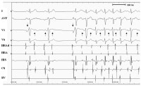
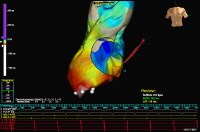
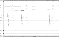
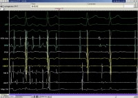
Propagation map of right atrial tachycardia originating from the right atrial appendage obtained with non-contact mapping using Ensite mapping system. This 12-lead electrocardiogram demonstrates an atrThis 12-lead electrocardiogram demonstrates an atrial tachycardia at a rate of approximately 150 beats per minute. Note the negative P waves in leads III and aVF (upright arrows) are different from the sinus beats (downward arrows). The RP interval exceeds the PR interval during the tachycardia. Note also that the tachycardia persists despite the atrioventricular block. Note that the atrial activities originate from theNote that the atrial activities originate from the right atrium and persist despite the atrioventricular block. These features essentially exclude atrioventricular nodal reentry tachycardia and atrioventricular tachycardia via an accessory pathway. Note also that the change in the P wave axis at the onset of tachycardia makes sinus tachycardia unlikely. Anterior-posterior projection is shown. An exampleAnterior-posterior projection is shown. An example of activation mapping using contact technique and EnSite system. The atrial anatomy is partially reconstructed. Early activation points are marked with white/red color. The activation waveform spreads from the inferior/lateral aspect of the atrium thought the entire chamber. White points indicate successful ablation sites that terminated the tachycardia. TV – Tricuspid valveCS – Shadow of the catheter inserted in the coronary sinus Intracardiac tracings showing atrial tachycardia bIntracardiac tracings showing atrial tachycardia breaking with application of radiofrequency energy. The local electrograms in the successful site preceded the surface P wave by 51 ms, consistent with successful site. Note that postablation electrograms on the ablation catheter is inscribed well past the onset of sinus rhythm P wave. The first 3 tracings show surface electrocardiograms as labeled.CS – Respective pair of electrodes of the coronary sinus catheterCS 7,8 – Located at the os of the coronary sinusCS 1,2 – Distal pair of electrodes Abl – Ablation catheter (D-distal pair of electrodes) An example of rapid atrial tachycardia mimicking aAn example of rapid atrial tachycardia mimicking atrial flutter. Single radiofrequency application terminates the tachycardia. The first 3 tracings show surface electrocardiograms, as labeled. HRA – High right atrial catheterRVA – Catheter located in right ventricular apexHBED and HBEP – Respectively, distal and proximal pair of electrodes in the catheter located at His bundleAblD and AblP – Respectively, distal and proximal pair of electrodes of the mapping catheterMAP – Unipolar electrograms from the tip of the mapping catheter

ابلیشن ریتم فلاتر (فارسی)

به دو دسته تقسیم میشود.Typical  و Atypical

1-Typical Flutter :آریتمی وابسته به ناحیه ایسم است

2-Atypical Flutter:آریتمی در اطراف اسکار های بافت ناشی

از فیبروز یا جراحی است

Typical Flutter

1-HR>150 bpm

2-p wave rate>240- 360 bpm

3-پاسخ بطنی 2:1 یا 4:1 است

4-CCW(counter clock wise micro reentry )

5-مکان:دهلیز راست

مشخصات ECG:

1-P WAVE  منفی در لید های تحتانی (II-III-AVF )

2-P WAVE  مثبت در V1

3-SAWTOOTH P waves

4- موج p  از ایسم منشا میگیرد بنابراین اولین

سیگنال  A  از  CS  پروگزیمال و یا روی کاتتر  HIS  است

 و  activation A در  cs از پروگزیمال به دیستال میرود.

Atypical Flutter

1-ریت سریع تر از نوع اول است  p rate :340-440

2-در اطراف انسزیون های جراحی است.functional

3-شبیه به ریتم AF  است.

4-معمولا SIGNAL A  در HAILLO  در 1 جلوتر است.

مشخصات ECG:

1-P wave  مثبت در لیدهای تحتانی

2-P wave  منفی در v1

Induction AFL

برای ایجاد اریتمی در لابراتوار الکتروفیزیولوژی

با cL حدود 20-30  میلی ثانیه کمتر از سرعت

اریتمی از دهلیز پیس میکنیم.

Flutter AblationTypical

هدف:بازگشت ریتم سینوسی به همراه بلوک دو طرفه

 یا  bidirectional  ناحیه ایسموس است.

سیگنال:در نمای  LAO معمولا نمای ساعت گونه 5.5 تا 7 

  با سیگنال ( A  کوچک و  V بزرگ ) شروع میکنیم و کاتتر

 ابلیشن را اهسته معمولا بعد از 90 ثانیه یا تا از بین رفتن

 سیگنال ها به سمت IVC  عقب میکشیم تا لاین کامل شود .

مدت زمان ارسال رادیوفرکانسی یا نحوه قرار دادن کاتتر

ابلیشن میتواند در پزشکان مراکز مختلف تفاوت داشته باشد.

علامت بلوک کامل ناحیه ایسموس:

برا ی حصول اطمینان از بلوک کامل ناحیه ایسم .یکبار از  

CS 9-10  و یک بار از HAILLO 1-2 پیس میکنیم در صورت

بلوک کامل هدایت A  به صورت پلکانی است. اما در

صورت وجود  gap  هدایت A به صورت پرانتزی است

و به این معنی است که هنوز ناحیه ایسم قابلیت

هدایت سیگنال را دارد و باید به ابلیشن ادامه داد.

امیدوارم توضیحاتم مثمر ثمر باشد


Atrial Flutter

Atrial flutter (AFL) is an abnormal heart rhythm that occurs in the atria of the heart.[1] When it first occurs, it is usually associated with a fast heart rate or tachycardia (beats over 100 per minute),[2] and falls into the category of supra-ventricular tachycardias. While this rhythm occurs most often in individuals with cardiovascular disease (e.g. hypertension, coronary artery disease, and cardiomyopathy), it may occur spontaneously in people with otherwise normal hearts. It is typically not a stable rhythm, and frequently degenerates into atrial fibrillation (AF). However, it does rarely persist for months to years

Atrial flutter
Classification and external resources

Classification

There are two types of atrial flutter, the common type I and rarer type II.[4] Most individuals with atrial flutter will manifest only one of these. Rarely someone may manifest both types; however, they can only manifest one type at a time.


Type I

Type I atrial flutter, also known as common atrial flutter or typical atrial flutter, has an atrial rate of 240 to 350 beats/minute. However, this rate may be slowed by antiarrhythmic agents.

The reentrant loop circles the right atrium, passing through the cavo-tricuspid isthmus - a body of fibrous tissue in the lower atrium between the inferior vena cava, and the tricuspid valve. Type I flutter is further divided into two subtypes, known as counterclockwise atrial flutter and clockwise atrial flutter depending on the direction of current passing through the loop.

  • Counterclockwise atrial flutter (known as cephalad-directed atrial flutter) is more commonly seen. The flutter waves in this rhythm are inverted in ecg leads II, III, and aVF.
  • The re-entry loop cycles in the opposite direction in clockwise atrial flutter, thus the flutter waves are upright in II, III, and aVF.

Catheter ablation of the isthmus is a procedure usually available in the electrophysiology laboratory. Eliminating conduction through the isthmus prevents reentry, and if successful, prevents the recurrence of the atrial flutter.

Type II

Type II flutter follows a significantly different re-entry pathway to type I flutter, and is typically faster, usually 340-350 beats/minute.[5] Left atrial flutter is common after incomplete left atrial ablation procedures.

به ادامه مطلب مراجعه بفرمایید         

ادامه نوشته

In appropriate sinus tachycardiaمتن فارسی

In appropriate sinus tachycardia

حالتی است که در ان میزان ضربان قلب با کوچکترین فعالیتی 140 تا

 150 bpm است در هنگام استراحت حدود 100bpm  ودر هنگام خواب

بین 80-90 bpm  است.فرد با کمترین فعالیتی دچار طپش قلب،

سرگیجه و یا تنگی نفسريا افت فشار خون هنگام ایستادن و تعریق  و

طبیعتا اضطراب و ناراحتی  میشود.در نوار قلب این افرا هیچ انورمالی

هدایتی مشاهده نمیشودبرای تشخیص کامل این حالت ابتدا بایستی

بیماری هایی که تاکیکاردی سینوسی می دهند را رد کرد مانند بیماری

هایپر تیروییدی-سو مصرف برخی مواد-دیابت و

فیوکروموسیتوما...همچنین می باید بین این حالت و SVT  تمایز

نمود.این حالت بیشتر در خانم ها ی بین 20-30 سال شایع می

باشد.علت ان به درستی معلوم نیست برخی ان را ناشی از بیماری

گره سینوسی و برخی ناشی از اختلال در سیستم عصبی اتوماتیک

میدانند.

روش های درمان

1-در مان دارویی:بتا بلاکرها معمولا اثر خوبی دارند-  کلسیم بلاکر ها

نیز می توانند  فعالیت گره سینوسی راکم کنند

2-ابلیشن: با تعدیل modify  یا ابلیشن گره سینوسی انجام میشود در

کاتتر ابلیشن سیگنالی را اندتخاب میکنند A  activation  از همه  early 

 تر باشد.این عمل در 80 % موارد موفقیت امیز بوده ولی قابل ذکر است

که ریسک عود ان نیز بالا می باشد

3-افزایش میزان نمک خوراکی برای حفظ حجم خون در گردش که باید با

مشورت پزشک معالج باشد

4-برخی از پزشکان معتقدند که این بیماران نیاز به مداخله خاصی

ندارند چون با افزایش سن نشانه های بهبودی افزایش میابد

Inappropriate sinus tachycardia

What is Inappropriate Sinus Tachycardia?

Inappropriate sinus tachycardia (IST) is a condition in which an individual's resting heart rate is abnormally high (greater than 100 beats per minute), their heart rate increases rapidly with minimal exertion, and their rapid heart rate is accompanied by symptoms of palpitations, fatigue, and exercise intolerance. IST is not associated with an abnormal electrical pattern on the ECG. The heart rhythm in IST appears to arise from within the sinus node, the cardiac structure that generates the normal heart rhythm. (Click here for a quick and easy review of the normal heart rhythm.)

What are the characteristics of IST?

While IST can be seen in anybody, it is most often a disorder of young women. The average IST sufferer is a woman in her late 20s or early 30s who has been having symptoms for months to years. In addition to the most prominent symptoms of palpitations, fatigue and exercise intolerance, IST can also be associated with a host of other symptoms including a drop in blood pressure upon standing, blurred vision, dizziness, tingling, shortness of breath, and sweating.

These patients most often have a resting heart rate of greater than 100 beats per minute, but it characteristically drops to 80 – 90 beats per minute while they are asleep. With even minimal exertion, the heart rate rapidly accelerates to 140 – 150 beats per minute. Palpitations (an unusual awareness of the heart beat) are a prominent symptom even though (as is often the case) there are no “abnormal” heart beats occurring. The symptoms experienced by sufferers of IST can be quite disabling and anxiety-producing.

IST was recognized as a syndrome only as recently as 1979, and has been generally accepted as a true medical entity only for the past 10 years or so. And even today, while IST is fully recognized as a genuine medical condition by every university medical center, many practicing physicians either haven’t heard of it or write it off as a psychological problem.

What causes IST?

Nobody knows.

The main question seems to be whether IST represents a primary disorder of the sinus node, or whether it represents a more general derangement of the autonomic nervous system – a condition called dysautonomia. Click here for a general description of the dysautonomia disorders.

Patients with IST are hypersensitive to adrenaline, such that a little bit of adrenaline (like a little bit of exertion) causes a marked rise in heart rate. There is evidence that the sinus node itself has structureal changes. But much other evidence suggests that a more general dysautonomia is present in these patients. (This would explain why symptoms most often seem out of proportion to the increase in heart rate.)

It is the notion that the sinus node itself is intrinsically abnormal that has led electrophysiologists to resort to ablation of the sinus node as a treatment for IST (more on this below).


What else needs to be considered in diagnosing IST?

Several other specific and treatable medical disorders can be confused with IST, and in a patient presenting with an abnormal sinus tachycardia, these other causes need to be ruled out. These disorders include hyperthyroidism, pheochromocytoma, diabetes-induced autonomic dysfunction, and substance abuse. These conditions generally can be ruled out with blood and urine tests.

In addition, other abnormal heart rhythm disorders – various types of SVT – can sometimes be confused with sinus tachycardia. Such SVTs need to be ruled out, because they can often be treated quite definitively.

ادامه نوشته

T wave alternans لینک

http://www.wikidoc.org/index.php/T_wave_alternans

برای دیدن مطلب کامل در مورد T wave alternans بر روی لینک فوق کلیک کنید

T-wave alternans is a beat-to-beat alternation in the repolarization cycle of the heartbeat. It can be observed in the electrocardiogram (ECG) as a difference in the amplitude and morphology of the ST-segment and/or the T wave among successive odd and even beats in an ABAB pattern (Figure).

سیگنال اوریج SAECG

سیگنال اوریج SAECG

در قسمت الکتروفیزیولوژی برای اندازه گیری ventricular late potential  به کار میرود.امواج  late potential  به اندازه 1-25   میکروولت و در صورت وجود در انتهای  کمپلکس  QRS  وجود دارند.و برای تشخیص بیمارانی که در معرض  خطر تاکیکاردی بطنی خود به خود متعاقب انفارکتوس میوکارد و یا بروز SVT بر اثر تحریک الکتریکی ،مفید است. دستگاه سیگنال اوریج در حقیقت این امواج را تقویت،ثبت  و مقایسه کرده سیگنال های ناشی از پارازیت را حذف کرده و معیار ها را بیان میکند مقادیر نرمال اندازه گیری در ذیل آمده است

HFLA: high frequency,low amplitude<39

QRS duration: male< 114       female<120

RMSO4: root mean square>20

 پروسیجر غیر تهاجمی است و مراحل ان مانند گرفتن نوار قلب است. مدت ان 20  دقیقه است و در طی این مدت بیمار بر روی تخت خوابیده است .محل قرار گیری الکترود ها در برخی از دستگاه ها با نوار قلب متفاوت است و در سینه، گردن و پشت قفسه سینه قرار میگیرد.آمادگی خاصی قبل از انجام لازم نیست. بهترکه سینه بیماران تمیز و شیو شده باشد .سیگنال اوریج در بیمارانی که ریتم انها  PVC  زیاد دارد و بیمارانی که پیس دارند قابل قبول نیست.سایر کاربرد های سیگنال اوریج در متن انگلیسی ذکر شده است که در صورت علاقه مطالعه شود.

What is a signal-averaged electrocardiogram

Signal-Average Electrocardiogram

(Signal-Averaged ECG, Signal-Averaged EKG, SAECG)

Procedure Overview

What is a signal-averaged electrocardiogram?

An electrocardiogram (ECG or EKG) is one of the simplest and fastest procedures used to evaluate the heart. Electrodes (small, plastic patches) are placed at certain locations on the chest, arms, and legs. When the electrodes are connected to an ECG machine by lead wires, the electrical activity of the heart is measured, interpreted, and printed out for the physician's information and further interpretation.

A signal-averaged electrocardiogram is a more detailed type of ECG. During this procedure, multiple ECG tracings are obtained over a period of approximately 20 minutes in order to capture abnormal heartbeats which may occur only intermittently. A computer captures all the electrical signals from the heart and averages them to provide the physician more detail regarding how the heart’s electrical conduction system is working.

Signal-averaged ECG is one of several procedures used to assess the potential for dysrhythmias/arrhythmias (irregular heart rhythms) in certain medical situations.

Other related procedures that may be used to assess the heart include resting electrocardiogram (ECG), Holter monitor, exercise electrocardiogram (ECG), cardiac catheterization, chest x-ray, computed tomography (CT scan) of the chest, echocardiography, electrophysiological studies, magnetic resonance imaging (MRI) of the heart, myocardial perfusion scans, radionuclide angiography, and ultrafast CT scan. Please see these procedures for additional information.

The heart's electrical conduction system:

The heart is, in the simplest terms, a pump made up of muscle tissue. Like all pumps, the heart requires a source of energy in order to function. The heart's pumping action comes from an intrinsic electrical conduction system.

Illustration of the electrical system of the heart

An electrical stimulus is generated by the sinus node (also called the sinoatrial node, or SA node), which is a small mass of specialized tissue located in the right atrium (right upper chamber) of the heart.

The sinus node generates an electrical stimulus regularly at 60 to 100 times per minute under normal conditions. This electrical stimulus travels down through the conduction pathways (similar to the way electricity flows through power lines from the power plant to your house) and causes the heart's lower chambers to contract and pump out blood. The right and left atria (the two upper chambers of the heart) are stimulated first and contract a short period of time before the right and left ventricles (the two lower chambers of the heart).

The electrical impulse travels from the sinus node to the atrioventricular (AV) node, where impulses are slowed down for a very short period, then continues down the conduction pathway via the “bundle of His” into the ventricles. The “bundle of His” divides into right and left pathways to provide electrical stimulation to both ventricles.

This electrical activity of the heart is measured by an electrocardiogram. By placing electrodes at specific locations on the body (chest, arms, and legs), a graphic representation, or tracing, of the electrical activity can be obtained. Changes in an EKG from the normal tracing can indicate one or more of several heart-related conditions.

Reasons for the Procedure

Reasons your physician may request a signal-averaged ECG may include, but are not limited to, the following:

  • to determine the cause of chest pain
  • to evaluate other signs and symptoms which may be heart-related, such as fatigue, shortness of breath, dizziness, or fainting
  • to help identify irregular heartbeats
  • for further evaluation of dysrhythmias/arrhythmias noted on resting ECG

There may be other reasons for your physician to recommend a signal-averaged ECG.

Risks of the Procedure

A signal-averaged ECG is a quick, noninvasive method of assessing the heart’s function. Risks associated with ECG are minimal and rare.

Prolonged application of the adhesive electrode patches may cause tissue breakdown or skin irritation at the application site.

There may be other risks depending upon your specific medical condition. Be sure to discuss any concerns with your physician prior to the procedure.

Certain factors or conditions may interfere with or affect the results of the test. These include, but are not limited to, the following:

  • obesity, pregnancy, or ascites (accumulation of fluid in the abdomen)
  • anatomical considerations such as the size of the chest and the location of the heart within the chest
  • movement during the procedure
  • exercise, intake of high-carbohydrate meal, and/or smoking prior to the procedure
  • certain medications
  • electrolyte abnormalities, such as too much or too little potassium, magnesium, and/or calcium in the blood

Before the Procedure

  • Your physician or the technician will explain the procedure to you and offer you the opportunity to ask any questions that you might have about the procedure.
  • Generally, fasting is not required before the test.
  • Notify your physician of all medications (prescribed and over-the-counter) and herbal supplements that you are taking.
  • Notify your physician if you have a pacemaker.
  • The area(s) where the electrodes are to be placed may be shaved.
  • Based upon your medical condition, your physician may request other specific preparation.

During the Procedure

A signal-averaged ECG may be performed on an outpatient basis or as part of your stay in a hospital. Procedures may vary depending on your condition and your physician’s practices.

Generally, a signal-averaged ECG follows this process:

  1. You will be asked to remove any jewelry or other objects that may interfere with the procedure.
  2. You will be asked to remove clothing from the waist up. The technician will ensure your privacy by covering you with a sheet or gown and exposing only the necessary skin.
  3. You will lie flat on a table or bed for the procedure. It will be important for you to lie still and not talk during the procedure, so as not to interfere with the tracing.
  4. If your chest is very hairy, the technician may shave small patches of hair, as needed, so that the electrodes will stick closely to the skin.
  5. Electrodes will be attached to your chest, abdomen, and back.
  6. The lead wires will be attached to the skin electrodes.
  7. Once the leads are attached, the technician may key in identifying information about you into the machine's computer.
  8. The EKG will be started. Generally, it will take about 20 minutes to obtain the necessary ECG information.
  9. Once the tracing is completed, the technician will disconnect the leads and remove the skin electrodes.

After the Procedure

You should be able to resume your normal diet and activities, unless your physician instructs you differently.

Generally, there is no special care following a signal-averaged ECG.

Notify your physician if you develop any signs or symptoms you had prior to the test (e.g., chest pain, shortness of breath, dizziness, or fainting).

Your physician may give you additional or alternate instructions after the procedure, depending on your particular situation.

مکان های مسیر فرعی سندرم ولف پارکینسون وایت(متن فارسی)

اختلال الکتروکاردیوگرافی سندرم Wolf Parkinson White (WPW زمانی به وجود می آید که تحریک دهلیزی تمام یا قسمتی از بطن ها یا تحریک بطنی، تمام یا قسمتی از دهلیز را زودتر از زمانی فعال کند که از انتقال تحریک از مسیر هدایتی تخصیص یافته طبیعی انتظار می رود. این فعال شدن زودرس به وسیله ارتباطات عضلانی ایجاد می شود که در حقیقت فیبرهای میوکاردی هستند که در خارج از بافت هدایتی تخصیص یافته قرار دارند و مسیرهای فرعی نامیده می شوند. به این اختلال زمانی سندرم تلقی می شود که به علت وجود مسیر فرعی، تاکی آریتمی ایجاد گرد

بروز سندرم ولف پارکینسون وایت تا 3 در هزار هم گزارش شده است. اغلب افراد مبتلا به سندرم WPW قلب سالم دارند و بروز تاکی آریتمی ها می تواند حیات آ نها را به خطر اندازد و حتی احتمال وقوع مرگ ناگهانی با فرکانس تخمینی 1/0% وجود دارد. تعدد تاکی کاردهای حمله ای با افزایش سن بیشتر می شود.


در زمینه انتخاب درمان، درمانهای دارویی آنتی آریتمیک از زمانهای قدیم برای سندرم WPW وجود داشته و هر چند با موفقیت هایی همراه بوده، اما کاملاً مطلوب نبوده است. با مصرف این داروها کاهش در بروز مرگ ناگهانی قابل پیش بینی نبوده و در مصرف کوتاه مدت و درازمدت، عوارض متعددی ایجاد می گردد. امروزه برای بررسی تشخیص و درمان آریتمی ها بررسی الکتروفیزیولوژیک قلب (EPS) Electro Physiologic Study و استفاده از انرژی رادیوفرکونسی، نقش عمده ای پیدا نموده است. در مطالعات انجام شده، (Radiofrequency Catheter Ablation) RFCA زمانی که توسط الکتروفیزیولوژیست های بالینی ماهر انجام گردیده، بسیار بی خطر و نتایج عالی به همراه داشته است اثربخشی، بی خطری و به صرفه بودن این روش درمانی، آن را به درمان انتخابی تبدیل کرده است

بیماران ممکن است علایمی چون طپش قلب،درد قفسه سینه، سنکوپ،SCD  را تجربه نمایند

در الکتروکاردیوگرام شاهد وجود  PR interval  کوتاه – موج دلتا – افزلیش اندازه  QRS  هستیم.

تاکی کاردی در WPW به دو صورت ارتودرومیک( طرح  LBBB  ) و یا انتی درومیک ( طرح  RBBB ) در  V1 است.

در تعیین محل WPW الکتروکاردیوگرام هم می تواند کمک کننده و هم گمراه کننده باشد . معمولا در انهایی که دلتای کوچک دارند مسیر فرعی در سمت چپ  ودر دلتاهای بزرگ مسیر فرعی در سمت راست است ( این یک اصل کلی نیست).هنگامی که دلتا هست  HV کوتاه تر میشود.

 راهنمای مکان های مسیر فرعی:

Right free wall: دلتای مثبت در لید  I and avL به همراه  LEFT axis

Right antroseptal : دلتای مثبت در لید II – III  -avF

Left Free Wall : دلتای منفی در لید avL – I – V5 –V6   

Typical Right Postroseptal : دلتای ایزوالکتریک در  avF – III – II  و  وجود  rS در  V1  - وجود  Rs در  V2

نسبت  این دو موج در V1 –V2  تغییر میکند.(

.( transient zone

Right Postro Septal: دلتای منفی در لید II – III – avF


Wolff-Parkinson-White 2

WPW Syndrome stands for Wolff-Parkinson-White Syndrome. It is also called as Ventricular pre-excitation with arrhythmia. WPW syndrome is the most common type of ventricular pre-excitation syndromes. In normal conditions, the electrical signals in the heart move through the heart using a single path. It is as a result of the movement of electrical signals from the heart’s atria to the ventricles, the heart beat is caused. Therefore for the heart to beat properly, the timing of the electrical signals play a vital role. But in case of people with Wolff-Parkinson-White syndrome, as they are born with an extra connection in the heart, called an accessory pathway which allows electrical signals to go around the atrioventricular node and move from the atria to the ventricles faster than usual, this results in the arrival of the electrical signals to the ventricle sooner than it actually should. This condition is called the WPW syndrome. 

The WPW Syndrome comes under the category of heart’s electrical abnormality called the pre-excitation syndrome. It is usually recognized by the changes seen in the electrocardiogram. An electrocardiogram (ECG) is a graphical record that shows the heart’s electrical activity


WPW syndrome is categorized into two types depending on the ECG findings. They are the type A and the type B. Let us have a brief discussion on each one of them.


Type A

In this type of WPW syndrome, the delta wave and QRS complex are predominantly straight in the precordial leads. The dominant R wave in lead V1 may be misinterpreted as right bundle branch block.


Type B

The delta wave and QRS complex are predominantly negative in leads V1 and V2 and positive in the other precordial leads, resembling left bundle branch block.


Symptoms

There are cases wherein some people have WPW syndrome but do not know they have it because they do not experience any symptoms while there are cases where the patients may experience several symptoms. The common symptoms are:

Dizziness

Rapid heart beat

Shortness of breath

Chest palpitations        

Fainting

Cardiac arrest 

Causes

Wolff-Parkinson-White syndrome affects 1 in 1,000 people globally.  In most of the cases, the cause of WPW syndrome is unknown. However, there are cases which show a relation between the genes and the WPW syndrome though only a small percentage of WPW syndrome cases are said to run in families. 


Complications 

There are  very few complications of Wolff-Parkinson-White (WPW) syndrome. However, complications of WPW syndrome can occur at any age. But people who are born with an accessory pathway in the heart will never experience any serious health problems associated with the condition.


Diagnosis and Treatment

The diagnosis of WPW Syndorme is usually done using the electrocardiogram. Treatment of WPW syndrome depends on how severe the symptoms are. It also depends on the type of WPW syndrome the person is suffering from. Most of the time, the asymptomatic patients, that is the patients who are not troubled by symptoms, usually do not need any treatment. However, even though treatment is not necessary, it is very much important to be evaluated on a regular basis by the doctor.


WPW Syndrome

wpw syndrome
shows the heart’s electrical activity.

The ECG on the top shows normal sinus rhythm and the ECG at the bottom shows Wolff-Parkinson-White Syndrome.
normal sinus rhythm ecg
wpw syndrome ecg
Types of WPW Syndrome
 
 catheter ablation in wpw white syndrome
 

لینک کتابخانه الکتروکاردیوگرام

لینکی که در ذیل برایتان قرار داده ام بسیار جالب است و در واقع کتابخانه نوار قلب است .شما میتوانید نمونه الکتروکاردیوگرام های بیماران مراکز مختلف با دسته بندی تمامی اریتمی ها را انتخاب و مشاهده بفرمایید. امیدوارم برایتان مفید باشد .متاسفانه قرار دادن ان در وبلاگ با کیفیت بالا امکان پذیر نبود.لطفا بر روی لینک کلیک کنید.

http://www.ecglibrary.com/ecghome.html

left lateral  wpw     

Wolf-Parkinson-White syndrome


Wolf-Parkinson-White syndrome

  • short PR interval, less than 3 small squares (120 ms)
  • slurred upstroke to the QRS indicating pre-excitation (delta wave)
  • broad QRS
  • secondary ST and T wave changes

Localising the accessory pathway

An accessory pathway, bundle of Kent, exists between atria and ventricles and causes early depolarisation of the ventricle. The location of the pathway may be deduced as follows:-

  LOCATION                   V1   V2   QRS axis

left posteroseptal (type A)  +ve  +ve  left

right lateral      (type B)  -ve  -ve  left

left lateral       (type C)  +ve  +ve  inferior (90 degrees)

right posteroseptal          -ve  -ve  left

anteroseptal                 -ve  -ve  normal


لینک های Basics of Pacemaker Timing

Basics of Pacemaker Timing

:برای دیدن  موضوع به صورت پی دی اف  بر روی لینک دوم و به صورت اموزش ویدیویی بر روی لینک  اول کلیک کنید        

https://wwwp.medtronic.com/medtronicconnect/contentpacemaker-timing-01.html

http://www.cardiorhythm.com/2009/pdf/19/76.pdf

لینک بسیار مفید برای  یادگیری مکانیسم اریتمی ها

لینکی که در زیر مشاهده مکنید اریتمی های مختلف را به صورت انیمیشن قلب و همین طور نوار قلب نشان میدهد .برای مشاهده بر روی لینک ذیل کلیک نمایید

http://www.biosensewebster.com/patientEducation/av-nodal-reentrant-tachycardia.aspx

PJRT ECG 2

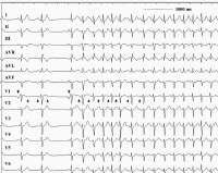
Note the regular, narrow complex tachycardia throughout. 

PJRT ECG

 shows an ECG from a 29-year patient with PJRT. The tachycardia was an incidental finding on a routine ECG and the patient was asymptomatic. The tachycardia is described as a long RP tachycardia (see below). The p wave looks different to sinus rhythm – it is typically inverted in the inferior leads (II, III and aVF) - indicating atrial activation from “low to high” (the opposite direction to sinus rhythm). The p-R interval is typically relatively normal 
PJRT

PJRT

characterized by a long RP′ interval

شبیه AVNRT  است اما به علت هدایت اهسته رتروگرد از راه فرعی تاکیکاردی اهسته است.

در ECG

1-موج  P منفی در لیدهای تحتانی وجود دارد.

2-سیگنال V با حالت تاخیری نسبت به  سیگنال  A  می اید.

3-مکان ابلیشن ناحیه پوستروسپتال است.

4-اولین A اریتمی در CS9-1O دیده میشود.

5-تفاوت ان باAVNRT  ان است که از FAST  رد نمیشود.

Permanent junctional reciprocating tachycardia (PJRT)

Permanent junctional reciprocating tachycardia (PJRT) is a rare form of nearly incessant supraventricular tachycardia occurring predominantly in infants and children and characterized by a long RP′ interval and, in the typical form, by negative P-waves in leads II, III, and aVF on the surface ECG. During sinus rhythm, the surface ECG is normal, without manifest pre-excitation. PJRT is caused by an atrioventricular (AV) re-entry using the AV node as the antegrade limb and a slowly conducting accessory pathway (AP) as the retrograde limb. The location of the AP is commonly right posteroseptal with an atrial insertion close to the ostium of the coronary sinus, but other locations have been reported. Chronic uncontrolled tachycardia has been reported to result in tachycardia-induced cardiomyopathy (TIC), which usually recovers with adequate ventricular rate control As PJRT is most of the time refractory to drug therapy, radiofrequency catheter ablation of the AP has become the treatment of first choice.

برای دیدن متن انگلیسی و اطلاعات بیشتر بر روی لینک ذیل کلیک کنید

www.inspire.com/conditions/permanent-junctional-reciprocating-tachycardia-pjrt

انواع AVNRT و درمان ان

انواع AVNRT

1-ATYPICAL AVNRT(SLOW-SLOW

در الکتروکاردیوگرام موج P در لیدهای تحتانی منفی است./ در لید های V1-V2-avR- avL  موج P مثبت است./ SHORT PR  است.

2-ATYPICAL AVNRT ( FAST-SLOW

LONG PR /موج  P در لید های تحتانی منفی / موج P  در لید های avL- avR مثبت است.

3- ATYPICAL  AVNRT( SLOW-FAST 

SHORT VA-LONG AV /P  قابل مشاهده وجود ندارد یا در  QRS پنهان شده و یا کاملا بعد از  QRS  میاید/

SUDO( S  در لید های تحتانی II,III, avF   / در V1  SUDO R/  ریتم منظم دارد.

درمان AVNRT

تحریک واگ ، ماساژ کاروتید، مانور والسالوا، مانور مالف  باعث

 کاهش سرعت اریتمی و یا قطع ان میشود.در صورت عدم

پاسخ آدنوزین اولین داروی انتخابی است. آدنوزین هدایت

رتروگرد را کند میکند و به صورت 12-6 میلی گرم تزریق سریع

میشود. در بیماران تعویض قلب و یا کسانی که دیپیریدامول

میگیرند 3 میلیگرم تزریق میشود..اگر آدنوزین جواب نداد شوک

سینکرونایز 10-50 ژول داده میشود. درمان ابلیشن :به طور

معمول با ابلیشن  SLOW PATHWAY  انجام میشوددر نوع ATYPICAL  میتوان  FASTPATHWAY  را ابلیت کرد که به علت

عوارض بالا انجام نمیشود.

سیگنال ابلیشن

بر روی کاتتر ابلیشن باید هر دو سیگنال  A/V را داشته باشیم از

عدم وجود سیگنال  HIS  اطمینان حاصل کنید. ابلیشن در ناحیه

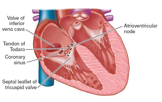
 SLOW PATH WAY  انجام میشود که به صورت اناتومیکی از

مثلث کخ که در شکل زیر نشان داده شده است استفاده

میشود .استفاده از نمای RAO  متداول تر است اما در برخی

مراکز از نمای  LAO  استفاده میشود.به خاطر داشته باشید که

راس مثلث مکان  HIS  و قاعده ان مکان  CS OS  است.نسبت ا

ندازه موج A/V بهتر است 3/1 باشد.همچنین در ابلیشن

 AVNRT  میتوان از سیگنال AP potential  که به صورت

دفلکشن کوچکی میان a/v  میاید نیز بهره برد. در حین ارسال

رادیو فرکانس در صورت ایجاد بلوک VA یا AV  ویا طولانی شدن

 PR  و یا ACCELERATED JUNCTIONAL RHYTHM  ارسال

امواج رادیوفرکانس را به سرعت قطع کنید. بهترین حالت ابلیشن

زمانی است که به تناوب ریتم جانکشن و سینوسی داشته

باشیم.

ایزوپرل

در هنگام مطالعه الکتروفیزیولوژی برای ایجاد اریتمی و افزایش

ریت بیمار طبق دستور پزشک  از ایزوپرل به صورت انفوژیون

آهسته و یا اتروپین استفاده میکنیم بالا رفتن ریت تا 20% ریت

پایه مناسب است.در هنگام دادن ایزوپرل به سرعت ریت و فشار

خون بیمار توجه کنید.بیمار ممکن است حالت هایی چون

گرگرفتگی،تنگی نفس،طپش قلب را تجربه نماید که در این صور

ت ایزوپرل و سایر سرم های دریافتی بیمار که باعث ورود دارو به

خط وریدی بیمار میشود را قطع کنید.نیمه عمر ایزوپرل کوتاه

بوده و بعد از چند دقیقه اثر ان از بین میرود.


اناتومی مثلث کخ

تاکی کاردی reentrant گره AV

تاکی کاردی reentrant گره AV

شایع ترین علت از تاکی کاردی فوق بطنی پروگزیمال AVNRT

 است. AVNRT است در  50-60% از بیمارانی که  QRS tachyarrhythmia منظم باریک داشته اند تشخیص داده شده

است . ضربان قلب  بین120-250  و کاملا منظم است که به طور

معمول  AVNRT ممکن است در افراد سالم جوان, و زنان رخ

می دهد. اغلب بیماران بیماری های قلبی ساختاری ندارد. اما,

گاهی اوقات این افراد ممکن است یک بیماری قلبی زمینه ای

مانند بیماری روماتیسمی قلب, پریکاردیت, انفارکتوس میوکارد,

پرولاپس دریچه میترال, یا سندرم preexcitation  داشته باشند

درتاکی کاردی دهلیزی گره reentrant. معمولابا محور طبیعی
 
 قلبی و امواج شبه S در II, III, و AVF. همچنین شبه R ’ امواج
 
 در V1 و AVR.دیده میشود این سیگنال ه نشان دهنده فعالیت
 
 رتروگراد دهلیزی می باشند.

درک الکتروفیزیولوژی بافت گره AV بسیار مهم است به منظور

درک مکانیسم AVNRTباید گفت که. در بیشتر افراد, گره AV

دارای یک مسیر هدایتی است که تحریکات را به

صورت  anterogradeهدایت مینماید.. در موارد خاص, بافت گره AV ممکن است 2 مسیر رسانا با خواص مختلف

الکتروفیزیولوژیک داشته  داشته باشد. یک مسیر (آلفا) مسیر

نسبتا آرام  با یک دوره کوتاه تحریک ناپذیری است, در حالی که

مسیر دوم : (بتا) مسیر سریع با یک دوره طولانی تحریک

ناپذیری است.عملکرد  اشتراکی این مسیرهای مختلف  به

عنوان راه فرعی برای تاکی کاردی reentrant عمل میکند.

شروع AVNRT با ضربه زودرس دهلیزی میباشد

150072 156670 3015 300x221 Paroxysmal Supraventricular Tachycardia
 

مهم, توجه داشته باشید که در AVNRT بطن ها به عنوان

بخشی از مدار  ورود مجدد درگیر نیستد;  از آنجا که این ضربه به

طور معمول در شیوه ای anterograde از طریق مسیر آهسته و

در صورت رتروگراد انجام از طریق مسیر سریعصورت میگیرد. 

فاصله PR طولانی تر از فاصله RP.است  بنابراین, در بیماران

مبتلا به AVNRT معمولی, موج P معمولا در انتهایی کمپلکس

 QRS قرار دارد. در بیماران مبتلا به AVNRT آتیپیک, هدایت

 anterograde از طریق مسیر سریع و هدایت رتروگراد از طریق

مسیر آهسته انجام میشود. بنابراین در بیماران آتیپیک, فاصله

 RP طولانی تر از فاصله   PR.است

محل ابلیشن AVNRT


Figure 3.  Schema of the AV node with radiofrequency energy delivered via an ablation catheter, typically at the site of the slow pathway to eradicate the circuit that initiates and perpetuates AVNRT.

-

AV nodal reentrant tachycardia (AVNRT)